Every four years, the Dutch hacker community gets together and organises an outdoor conference and festival. The most recent edition was Still Hacking Anyway (SHA2017), taking place August 4-8 on the scouting terrain in Zeewolde and drawing more than 3500 people from around the world. For four days the terrain was filled with all kinds of creative people, beautiful lighting, motorised sofa’s, flamethrowers, a very fast network connection, and an indescribable amount of amusement.
Ever since ‘Badgelife’ blew over from the US, electronic event badges have become a staple of European maker and hacker conferences alike. These can be as simple as solder-it-yourself boards that blink a LED, or as complex as fully-fledged software-defined radio’s which can be worn around the neck.
CCCamp 2015 ‘rad1o’ badge. Image: Christoph Krichenbauer.
Around 2016, organisation for SHA2017 slowly started up and I got involved in the team making a badge for visitors of the event. This is the story of the SHA2017 badge conception and design, how we managed to produce more than 4000 badges, and the challenges we encountered along the way.
Goals of the project
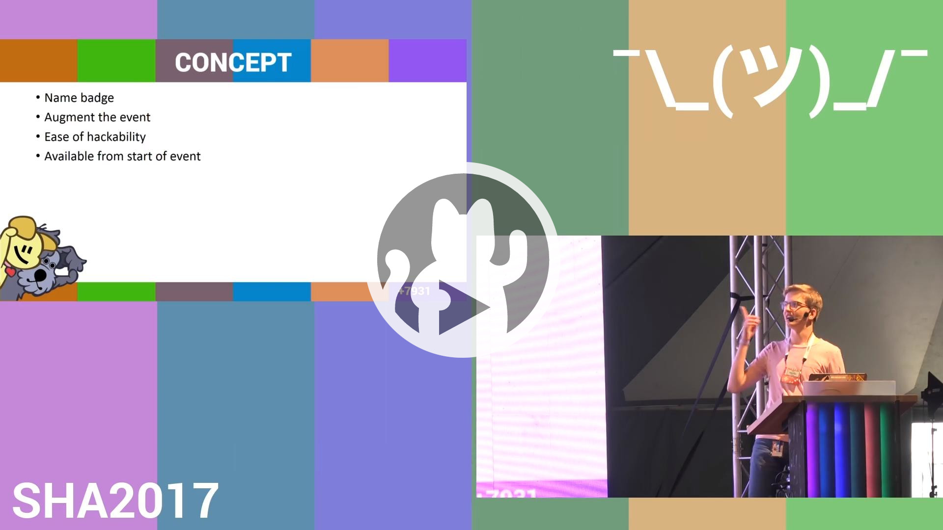
After a lot of brainstorming and inspiration from other events, we settled on the following list of requirements:
- The badge augments the event in some way.
- It functions as a name tag.
- Accessibility and ease of hackability are a priority.
- The badge needs to be useful after the event, and not disappear into a drawer.
EMF2016 ‘TiLDA MK3’ badge. Image: Marekventur.
While visiting Electromagnetic Field in 2016, we got our hands on the TiLDA MK3 badge. This ran MicroPython and had a way to download apps straight from the badge, meaning you didn’t need extensive toolchains or in-depth knowledge to get hacking on the badge. We decided to go for micropython as well, and added a few features to our concept:
- The badge should run MicroPython.
- Some kind of app-store should be available on the badge.
Development
As is usual for badge projects, the timeline cuts it very short. The final ideas around the badge only solidified around a year before the event. We didn’t get our first working prototypes until December 2016, about eight months before the event. A few months of the process need to be reserved for parts sourcing and production. Events like Chinese New Year can introduce a lot of delay in production, leaving us only a precious couple of months to make, revise, and finish the badge design. In addition, a lot of time is spent arranging sponsorship for components and production costs as we did not want to increase ticket costs to provide people with badges.
Looking back to the requirements, an app store requires connectivity so logically the badge should have WiFi too. Around this time, Espressif’s ESP8266 had just started flooding the hobbyist market. These were very affordable microcontrollers with WiFi built in, but they had limited memory and lacked a meaningful amount of GPIO and peripherals. We had a contact at Espressif who told us they were coming out with the much improved dual-core ESP32, and they might be able to sponsor us. At this point the chip had not entered mass production yet, but they had good hopes of delivering in time for our production (and to their credit, they did!).
The requirement of the badge functioning as a name tag calls for a display that is readable in bright sunlight outdoors, and a battery with sufficient life to last at least a day. A lot of conference badges use affordable liquid crystal displays (LCDs), but these are generally poorly readable in sunlight and they need a backlight which takes a lot of battery power. Organic LED (OLED) displays give an improvement in contrast and only lit pixels consume power, but they can still be a big power drain. We briefly looked at the expensive and difficult to get SHARP memory displays, but quickly settled on e-paper displays.
A selection of e-paper displays used in electronic price tags.
As the picture above shows, small e-paper displays can often be found in electronic supermarket price tags. They don’t need any backlight to have excellent visibility and contrast, and zero power is consumed when they display a static image. The downside is that they are very slow to refresh, taking seconds to draw a new frame while flashing the display between black and white multiple times. Some displays allow faster ‘partial’ refreshing or even refreshing small sections of the screen, but there is always a tradeoff between refresh speed and ghosting artifacts.
Slow display refreshes are fine when the badge is only used to display a name or something like a clock. For interaction with games or virtual keyboards faster refreshes are really necessary. The cheap (say, sub-€10) e-paper displays tend to officially only support ~3 second full refreshes, but with some hackery faster refreshes are possible. One of our team members reverse-engineered the look-up tables that the display controller uses internally, and managed to develop a way that gives much faster refresh rates (2-3 frames per second) at the expense of a lot of ghosting. This is fine though, as we can do slower full refreshes whenever time permits but faster refreshes can be used where speed is necessary.
If you’re looking for an in-depth overview of e-paper displays, check out this excellent video. In the video, Ben Krasnow details their operation and goes through essentially the same process as we did to obtain a higher refresh rate.
First prototype with ESP32 and e-paper display.
The image above shows our first custom PCB, which functioned as a sort of ESP32 and e-paper development board. The colourful side of the picture shows the first time we got this to successfully show anything on the display. The last picture was taken late December 2016, time was flying by and our initial target for production was only a few months away. Lots of work to be done, starting with some more fledged-out prototypes.
Line-up of badge revisions.
The picture above shows all badge revisions laid out chronologically, from prototype to production. After the first prototype, the badge shape was adjusted to fit the 2.96" displays we settled on. Capacitive touch buttons were added, taking inspiration from the old Game Boy designs. Six addressable RGBW LEDs were added above the display to match the SHA2017 ‘freedom flag’ design and that’s about all visible on the front.
Back of the production badge.
The back of the badge is arguably more interesting. It shows the ESP32 WROOM module, which Espressif specially produced with 16 MB of flash at our request. The ESP is programmed through a CP2102 USB-UART bridge, which will come back in a moment. Also visible is the 1000 mAh battery with protection and accompanying TP4056 charge controller, some other power circuitry and a bunch of passive components supporting the e-paper display. Beneath the battery sits a MPR121 capacitive touch IC which also works as a port expander to get the ESP32 some extra I/O. A small expansion header is centered on the board, breaking out power and a few useful signals.
Production
After the design was finalised, it was time to arrange production of the badge. Full PCB production (or at least assembly) in Europe would have had our preference, but this was prohibitively expensive and we could not find a fab house willing to sponsor the quantity we needed in time. Instead we opted to have the PCBs produced and assembled by PCBWay, who gave us with a discount in exchange for their logo on the badge. The remaining funding for production was provided by cash sponsors.
The most expensive part on the badge was the display. Quotes for the ‘GD’ brand displays we had used during development ranged from €6-8 per piece at large quantity, but a team member managed to track down a supplier (DKE) who offered a similar display for just over €4. We got our hands on a sample display and while it required a small change in the supporting hardware, we once again managed to implement partial refreshing. A solder jumper was added to the hardware design which lets you select between GD and DKE displays.
While the price for the displays was nearly cut in half by this switch, they still ended up costing us more than €20.000. In order to reduce cost in the rest of our Bill Of Materials (BOM), we reached out for help from a parts sourcing company operating in China. They were able to source a lot of our parts from local markets, saving us thousands compared to getting parts from western suppliers and shipping them to China for production. They also arranged logistics and eventually communication directly with PCBWay, and were generally an invaluable part in getting the badges ready in time for the event. I figure they currently have their hands full with the global parts shortage, but if you ever find yourself needing help sourcing components or arranging production, do yourself a favor and get in touch with ALLNET.
Around half May, after tons of back-and-forth and quotes around our BOM, we were finally making arrangements to get our latest design manufactured. I’ll forever be entertained by the depth of the reply chains we got into with PCBWay, resulting in email subject lines like
Re : Re: Re : Re: Re : Re: Re : Re: Re : Re: Re : Re: Re : Re: Re : Re: Re : Re: Re : Re: Re : Re: Re : Sponsorship SHA2017 Badge
or
Re : Re: Re : Re: Re : Re: Re : Re: Re : Re: Re : Re: Re : Re: Re : Re: Re : Re: Re : Re: Update of smt order.
Anyhow, I’m getting ahead of myself. Following the advice of jontyw (organiser of emfcamp and experienced badge-maker) we started with a small run of 18 badges to iron out issues before we went into mass production. This small quantity might have cost quite a bit, but it was absolutely worth it because we immediately found problems which would otherwise have probably scrapped the entire project right then and there.
USB connector issues.
Before even starting the test production run, we received the picture above from PCBWay. It turns out that the USB connectors we had supplied them with had a plastic locating peg, but there was no accompanying hole in our designs and all 4750 PCBs had already been manufactured. For the small run of 18 pieces they ended up just snipping the locating pegs off the connectors and soldering them by hand after running the boards through the assembly line, not to introduce any more delay. The rest of the connectors were exchanged for ones that would fit without modification. This was the first of several issues that we encountered, and PCBWay were excellent help in resolving them all one by one. They went to great lengths to provide us with functional boards.
By the time this sample run was completed we had already entered July. With the event less than a month away, the sample boards were rushed to shipping and we got testing as soon as we received them. We quickly discovered that we had under-specced the current rating of the PTC fuses, but that was easily fixed by changing one component in the BOM. More to our horror, only 8 out of 18 boards were functional in the first place. Some wouldn’t enumerate through USB, some had defective capacitive touch, and some had other problems still.
Underfilled solder pads on touch and serial IC.
Microscope inspection revealed that a lot of solder pads had been underfilled, as we hadn’t tested our solder paste stencil design properly before sending off the designs. We sent PCBWay some pictures indicating the issues. They experimented with different quantities of solder flux and were able to improve yield.
We finally gave the go-ahead for production on July 11th. After a few days, PCBWay got back to us saying that they were still having issues with underfill on two components and that the micro USB connectors were giving new issues. We hadn’t caught these issues before, because during the test run the connectors had been soldered by hand after the PCBs were already separated. When the panel was still intact, a small downwards lip on the connector would catch on the groove between individual boards. This angled the connector up and gave it a bad mechanical connection to the board.
Lip on micro USB connector catching on PCB panel grooves.
The amount of troubles that a single part can cause are staggering. Again, to their massive credit, PCBWay decided to rescue us by running the boards through the SMD assembly line without USB connectors attached, then separating the boards and soldering every single USB connector by hand and fixing any underfilled pads on the two problematic IC’s by hand as well. They decided not to charge us for this massive amount of extra work.
By this time, the e-mail subjects had escalated from ‘Very urgent about USB soldering’ to ‘Update: Very urgent’ and finally even ‘Very very urgent’. After discussing how to solve the last couple of assembly issues, PCBWay expedited production. They started started shipping boxes of badges a few days later, and by July 26th the last box of badges left China. We had a small scare when tracking showed that DHL had accidentally shipped the badges to Kazachstan, but we were able to pick them up from the depot just a day or two later.
Sweatshops & heroic volunteers
Boxes of badges and parts.
End of July, we had received about 500 kilograms of badges, displays, and parts, but we still had to put them all together in bags. During the process, all of the boards also had to be flashed with the firmware that our software team had been working hard on developing while we sorted production.
‘Sweatshop’ for assembling badge kits, attaching displays, and flashing firmware.
My co-teamlead Sebastius organised a few massive volunteer ‘sweatshops’ at RevSpace just before the event, with very well laid-out assembly lines. The first session was organised while we were still waiting for the first box of assembled PCBs. Even small tasks turn out to be a lot of work when you multiply them by five thousand, so we needed all the help we can get and spent more than half a day just filling ziplock bags with lanyards, batteries, double-sided tape, a strip of LEDs and flyers.
After we received the badges themselves, the sessions became a bit more exciting. We set up assembly lines to unpack the boxes of PCBs and plug a display into each badge. The badges were then plugged into a maze of USB hubs and cables around a couple of laptops running a script to automatically upload our latest firmware to the badges.
Flashing station, with a box of badges ready to be packed next to a pile of rejects.
After being flashed, the badge would run a small self-test. If all tests passed, it would display a nice image and move to the next station where the display was glued on and the badge finally zipped in the bags we prepared earlier. If a badge failed a test it was labelled with the type of defect, the display was unplugged from the badge, and it was put aside for repairs. After some small repairs, we ended up with a failure rate below two percent.
Boxes of badge kits, ready to ship to the event.
Just like the entire organisation of the event, everybody who came to the sweatshop was a volunteer just looking to help out. They made an absolutely heroic effort and without them the badge would not have been ready for camp. We obviously took good care of them in the form of food and drinks during the sweatshops, but to thank them we also handed out badge kits early. That way they could get a head start and publish some apps (or, for that matter, port an entire gameboy emulator to the badge) before the event started.
“CP2102” issues
It turns out that handing badge kits out early might have been the best decision we made throughout the entire project, because it uncovered a critical flaw present in about 2000 of our badges: they wouldn’t start on battery power.
The badge uses a CP2102 USB to UART IC. We had about 2500 genuine pieces sponsored by Silicon Labs, but had to source the other ~2000 ourselves. We didn’t mind buying less-than-genuine ICs to stay within budget, as the usual clones seemed to work just fine in our experience. Well, not so much this time.
The badges with genuine ICs worked fine. The others would work fine as long as they were getting power through USB. When USB was disconnected and the badge was powered from battery, it wouldn’t start. Here’s what we managed to piece together happened: This type of IC is usually ‘cloned’ by taking a general purpose microcontroller and programming it to emulate the behaviour of the original IC. This works decently for most uses, but you can’t really get around the hardware design of the microcontroller. The model used in this clone has input protection diodes on the I/O it uses for serial communication. When the ESP32 applies its logic voltage to these lines, the protection diodes conduct enough current to halfway power up the serial IC which in turn holds the ESP32 in reset.
Now the question: how do we fix this? There’s only a week or two before the event and we have two thousand good-as-bricked badges.
USB-Serial fix and accompanying repair efforts.
Considering the board design, the easiest fix was to take a scalpel, cut a trace and solder an 0402 resistor from the serial IC to a nearby via. This limits the current that can flow into the IC through the serial lines. Pictured above are the resistor bodge, and the fantastic volunteer effort in applying it 2000 times. We ran out of time to repair all defective badges before build-up of the event started, so the whole operation was moved to a tent on the event field where more people volunteered to solder tirelessly.
The badge project has been a series of very near misses, but in the end we produced more than 4000 functional badges and everybody who wanted one got it right at the gates where they entered SHA2017.
For more information on the cloned ICs and repair effort, check out this Twitter thread.
During the event
SHA2017 impression. Image: Waag, CC BY-NC-ND.
Visitors were presented with a ready-to-go badge kit. After plugging in the provided battery, the badge powers up and asks for the nickname of its owner. A quick over-the-air update and you are set with the latest firmware.
Happy badge owners inside the badge bar tent.
One of the big circus tents on the campsite was set up as ‘badge bar’ where people were welcome for support, to solder LEDs to their badges, to work on apps together or just to have a drink.
‘Wall of shame’ in the badge bar, showing the names of the poor people who dropped by for a display replacement and had their names immortalized as e-ink destroyers. Image: Jelly.
By the last day of the event, over 260 individual users had published nearly 300 MicroPython apps to the Hatchery, which could be downloaded right from the badge.
A few examples of what people wrote for the badge:
- An app to display the local weather forecast.
- An app to watch livestreamed talks (in grayscale, at three frames per second).
- Apps to monitor current temperatures measured in the on-site pizza oven and sauna.
- A massive multiplayer puzzle game, written in complete secrecy by one of our team members.
- Actual ransomware, which was unlockable by bringing a bottle of Club Mate to a specific tent. Great sports!
Live temperature monitoring of the on-site sauna. Image: Mikko Kenttälä.
Badge reception during the event was incredible. It was great to see so many people proudly displaying their nicknames, downloading and writing apps, and sharing their experiences.
After the event
Badge as a rain forecast display.![]()
Badge as a heart rate and altitude meter for the ‘Everest Run’ challenge. Project by Krzysztof.
Examples of ways in which people put their badges to use after the event include a display for live public transport information, using badges as event lighting controllers, and auto-updating exhibition labels using salvaged badges.
Recently, polyfloyd employed leftover badges to monitor CO2 levels in his hackerspace:
SHA2017 with add-on CO2 monitor PCB. Image: polyfloyd.
Even now, more than four years after the event, firmware updates are being released and new apps for the badge are still showing up.
Badge.team ecosystem
The SHA2017 badge spawned the “badge.team” collective. While I haven’t been involved since 2017, the team has been churning out new badges in the years following.
Furthermore, badge.team have developed an entire platform where ESP32-based badges can run the same base firmware and run the same apps. This prevents new badges from having to reinvent the wheel and improves long-term support.
Badges for the CampZone and Disobey hacker events were built around the badge.team firmware. In addition, the last Chaos Communication Camp badge runs a custom firmware but uses the badge.team hatchery as its app repository.
Closing words
This blog post has been a personal account of how events transpired four to five years ago leading up to the SHA2017 badge. It was impossible for me to describe every step of the process in detail, so feel free to contact me with any questions.
If you’d like a narrative closer to the event, you can watch the talk I gave together with Sebastius on the last day of SHA2017:
I would like to give a shout-out to the rest of the team behind the SHA2017 badge:
- Anne Jan Brouwer
- Bas van Sisseren
- Gavan Fantom
- Jeroen Domburg
- Markus Bechtold
- Sebastian Oort
- Thomas Roos
If you want to learn more about SHA2017, have a look at the website or press coverage. Jenny List wrote a nice review about the event which might aid in getting a better picture of what it’s like on the field.
Excited about visiting an event like this? MCH2022, the successor of SHA2017, will take place in the summer of 2022. Ticket sales should open around Christmas 2021. If you’d like to give a talk or organize a workshop, have a look at the Call for Participation which is open right now. Want to get involved in the organisation? Read the Vacancies and Volunteering Guide.
More coverage on the badge:
SHA2017 blog:
- “Call for sponsorship - the SHA2017 Badge needs your help!"
- “Talk announcement: The SHA2017 badge (The badge is a go!)"
- “SHA2017 Badge Stretch goals!"
- “BADGE: WORK IN PROGRESS”
Hackaday:
- “The SHA2017 Badge Revealed”
- “Hands On With The SHACamp 2017 Badge”
- “Make A Badge When There Is No Badge Yet”
- “A Four-Year-Old Event Badge Makes An Environmental Sensor”
Tweakers.net:
waag:
XS4ALL (sponsor):
transip (sponsor):
Espressif (sponsor):
PCBWay (sponsor):
Guardian360 (sponsor):