There is a famously long graduation holiday after finishing high school exams in the Netherlands. I was faced with one of those in 2015, and besides taking up a summer job in IT I used it to complete a couple of hobby projects I’d been working on for a while. My favourite one of those was building a clock using vintage nixie tubes.
Nixie tubes (or nixies) are early digital display tubes which display characters in the form of glowing neon gas. Though nixies have long been replaced by vacuum fluorescent, liquid crystal and later LED displays they remain my favourite way of displaying numbers as I am absolutely captivated by their warm orange glow. Though new nixies are being produced small scale, they’re prohibitively expensive at the moment. Fortunately it turns out that Soviet republics kept producing nixie tubes about a decade longer than the rest of the world, so it’s easy enough to get New Old Stock (NOS) tubes from eastern-european countries. Perusing eBay I found a lot of six tubes from Ukraine with date codes ranging from 1986 to 1988, and set out to make my own nixie clock.
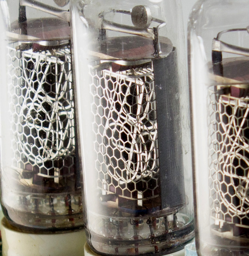
Nixie tube (click to enlarge)
A nixie tube as depicted above consists of metal electrodes sealed in a glass envelope along with a noble gas mixture. The honeycomb grid in the front serves as the anode, while the stamped metal digits behind it are cathodes. When a high voltage is applied between the anode and one of the cathodes, the neon gas around that digit starts to glow.
It turns out that nixies are quite difficult to drive compared to their modern replacements. For starters you need a high ionizing voltage to get them struck (usually 170-180 VDC), after which they exhibit negative resistive behaviour and usually maintain their glow at a lower voltage. My IN-14 tubes should strike starting at 170 V and maintain around 145 V with 2.5 mA cathode current. A usual topology will have the nixie tube connected to the high-voltage supply through an anode resistor, which reduces the voltage across the nixie tube to its sustaining voltage once struck and limits the cathode current.
I decided to split my clock design up into a stack of two boards to reduce its footprint, with the top board housing the nixie tubes themselves along with the cathode switches and the bottom board housing the power supply along with the microcontroller, time-keeping circuits and user interface.
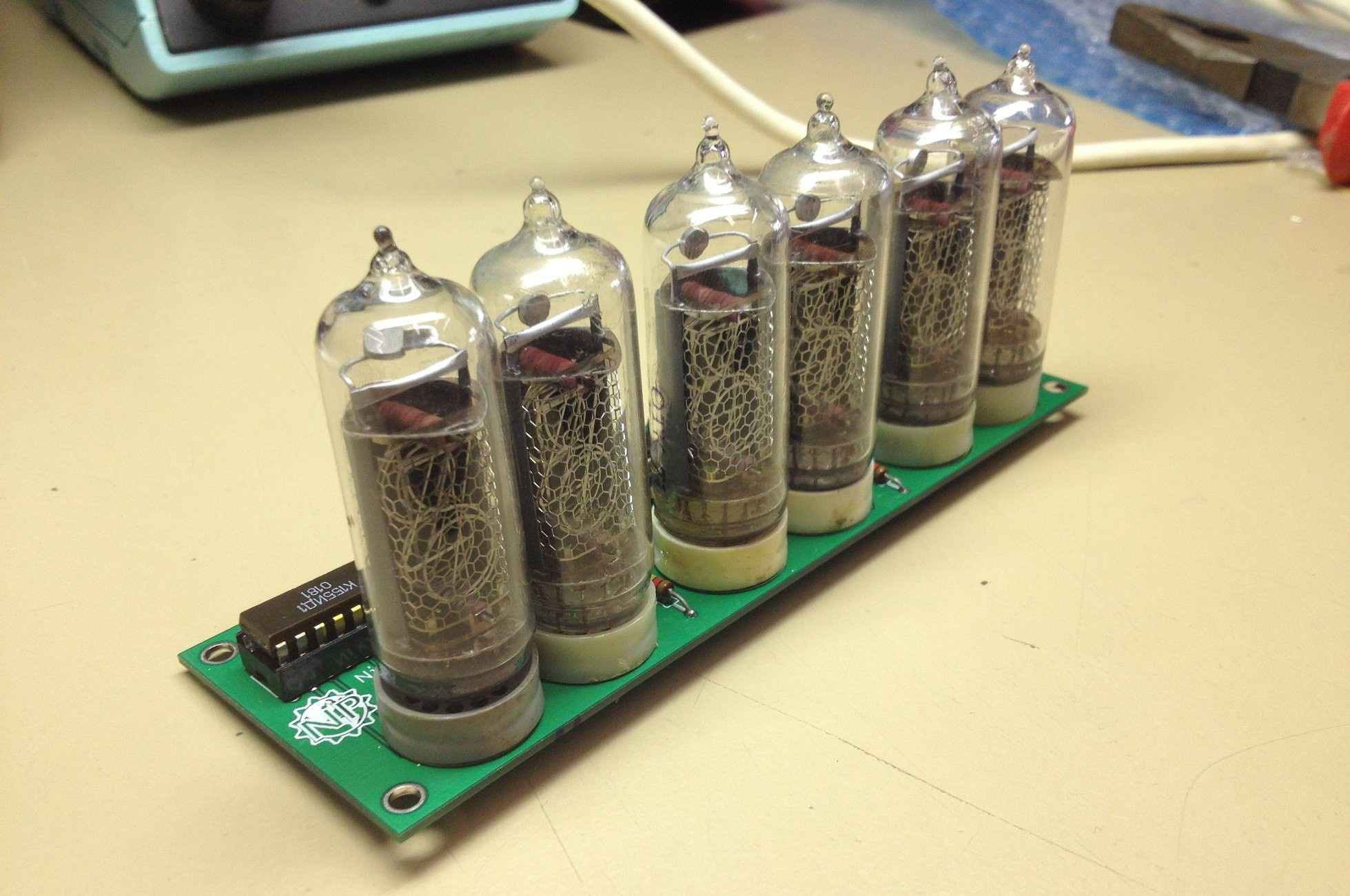
First top PCB
The first design of the top board is shown here, which has room for six nixie tubes along with a 74141 driver IC for each. The 74141 is a classic integrated circuit especially designed for cold-cathode tubes that had a BCD-to-decimal decoder along with a high-voltage transistor output stage for the ten nixie tube cathodes. Just like the nixie tubes, originals of this part were hard to get so I settled with the Soviet K155ID1 clones.
To this day I’m not completely sure if I was shipped defective driver ICs or if my layout was wrong in more ways than just getting the order of nixie tube cathodes wrong, but I never got this board design fully working. Anyhow, I wasn’t very happy with the design and the 6x4 bit BCD inputs would have required port expanders or shift registers on the bottom board so I set out to find a more suitable nixie driver IC.
After browsing nixie clock designs for a while, I found a part that was perfect for the task and better yet: still in production. The HV5812 is a 20-channel vacuum-fluorescent display driver with built-in shift register. VFDs are somewhat similar to nixie tubes, but they use an anode voltage up to 80 V. This means that we can’t use the HV5812 completely as intended, but with a little hacking it can drive nixie tubes without a problem.
The nixie tubes are supplied with 180 V through an anode resistor as usual. Instead of floating the cathodes which should remain off and pulling down the ones that should be on using an open-collector driver like the 74141 however, we use the HV5812 to actively drive the cathodes to 70 V or down to 0 V. With 60 V at a cathode, the difference between that cathode and the grid is less than the striking voltage so the digit remains off. When the cathode is pulled down to 0 V, the digit will turn on.
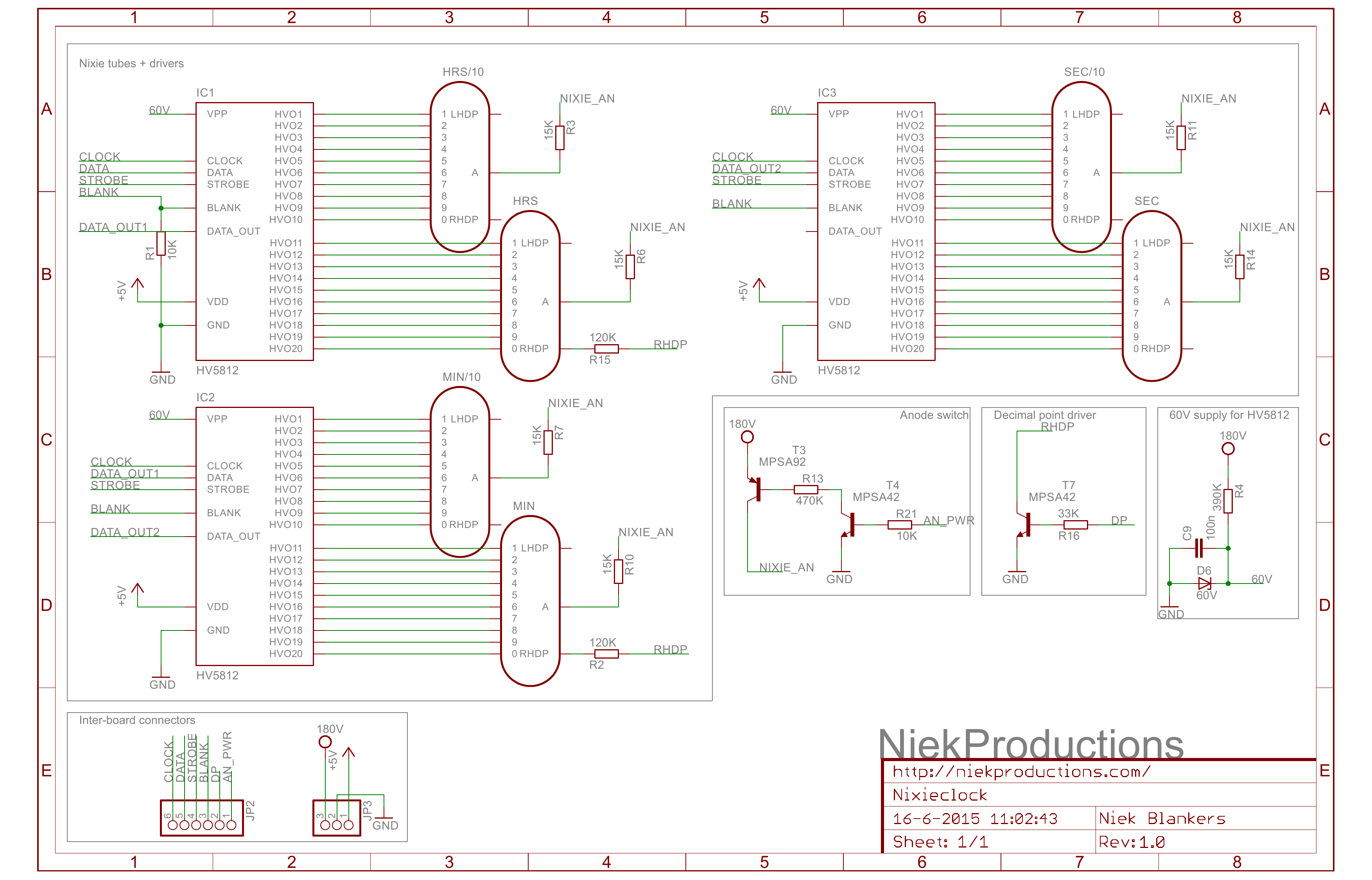
Top board schematic
The schematic for the top board is shown above. For ease of control no multiplexing is used, which means that there are three HV5812 drivers connected to two tubes each. The data inputs are chained together so that only a single serial line is required to feed all of them with data. A couple of high-voltage transistors are used both to drive the decimal points of two of the tubes as well as the anode voltage which can later be used to adjust the nixie tube brightness. This still leaves the small challenge of deriving a 60 V supply, but that is easily solved using a zener diode regulator as there should be little to none current drawn from this supply.
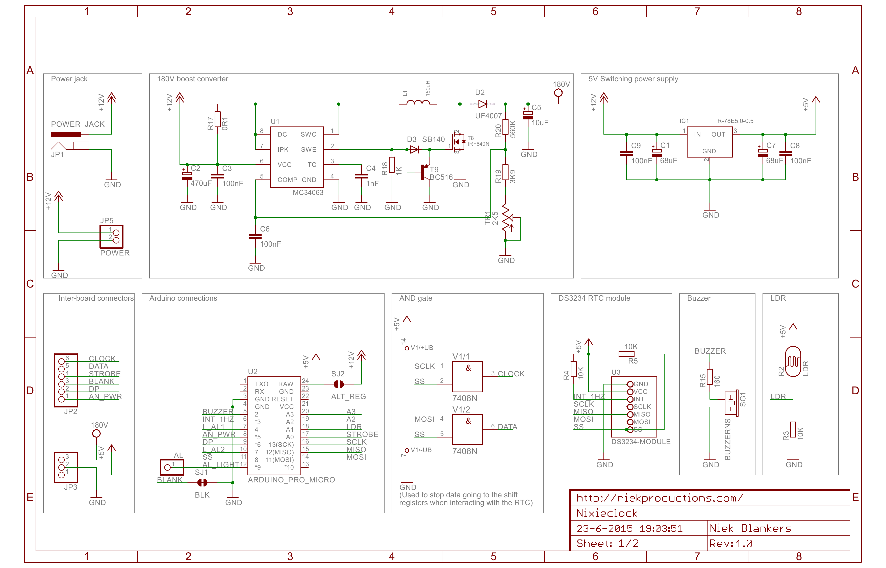
Bottom board schematic
Next it was time to design the bottom board. The first challenge, getting a 180 V supply from a 12 V input, is solved using a MC34063-based DC-DC boost converter. An Arduino Pro Micro board controls everything, and keeps time using an off-the-shelf DS3234 battery-backed Real-Time Clock (RTC) module. A light-dependent resistor (LDR) is used to sense ambient light, and a (highly annoying) piezo buzzer is used as an alarm. Not depicted is a resistor ladder with six buttons feeding into two remaining ADC channels, and two NE-2 neon tubes used for indicating the alarm clock state.
After painstakingly desoldering the nixie tubes from my first board design and moving them to the new top board, I verified its function and moved on to assembling the bottom board and the rest of the clock. I sandwiched the PCBs between a couple of laser-cut acrylic plates for protection (the circuit boards don’t need much protection, it’s mostly there to prevent you from getting zapped by 180 V while trying to disable the alarm or set the time).
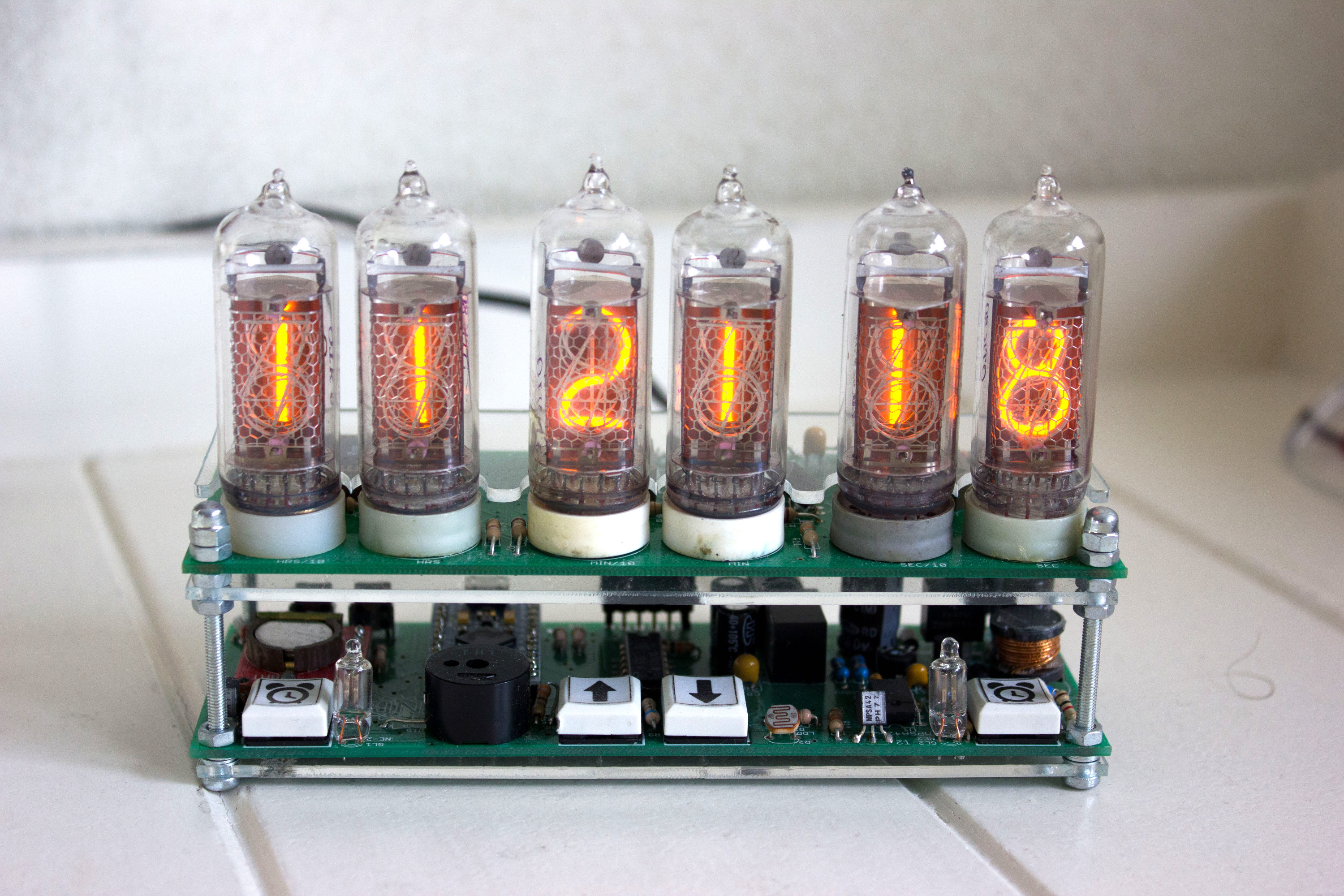
I took a couple nice shots of the assembled clock. After admiring those, please continue reading to hear about the code.
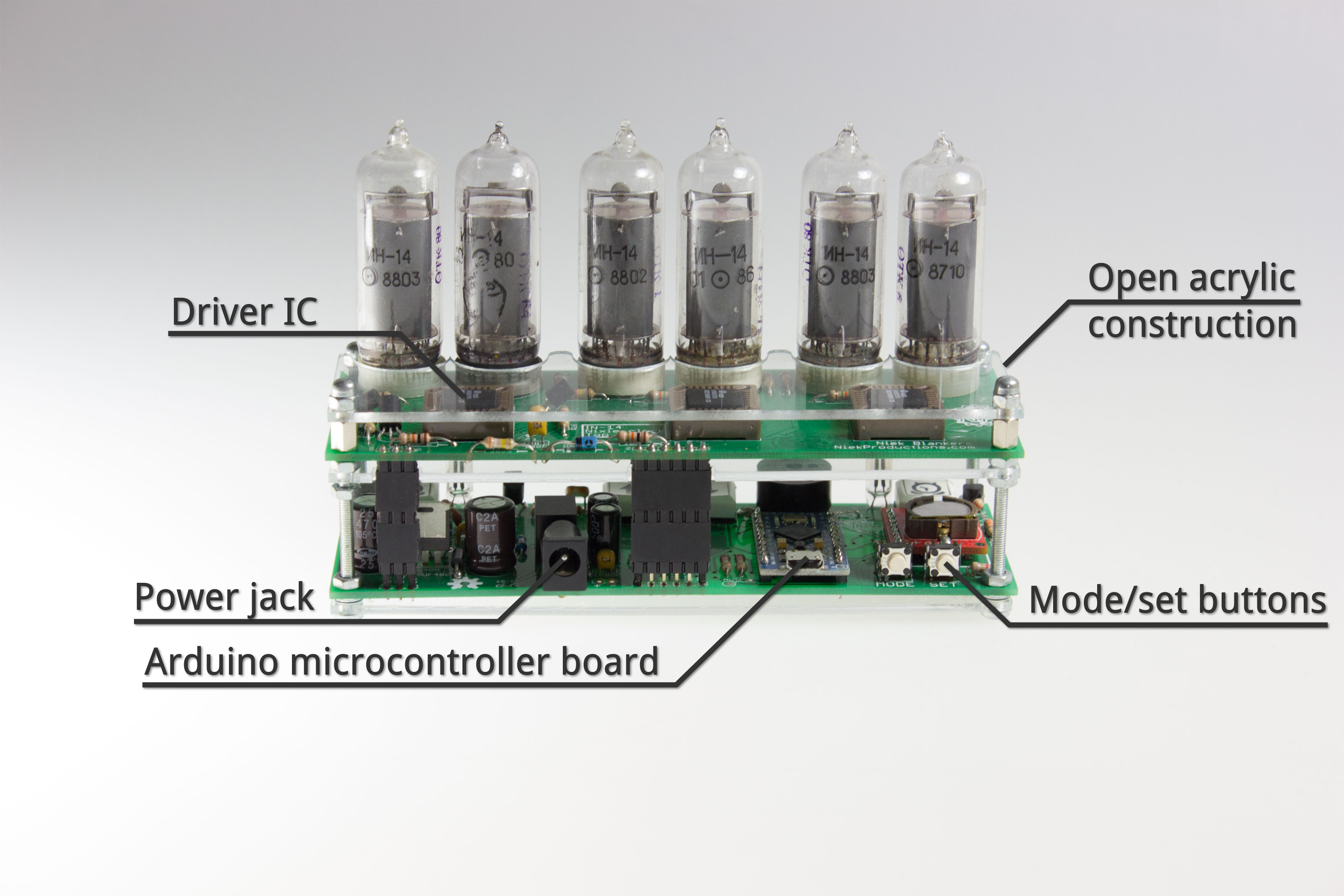
Front view
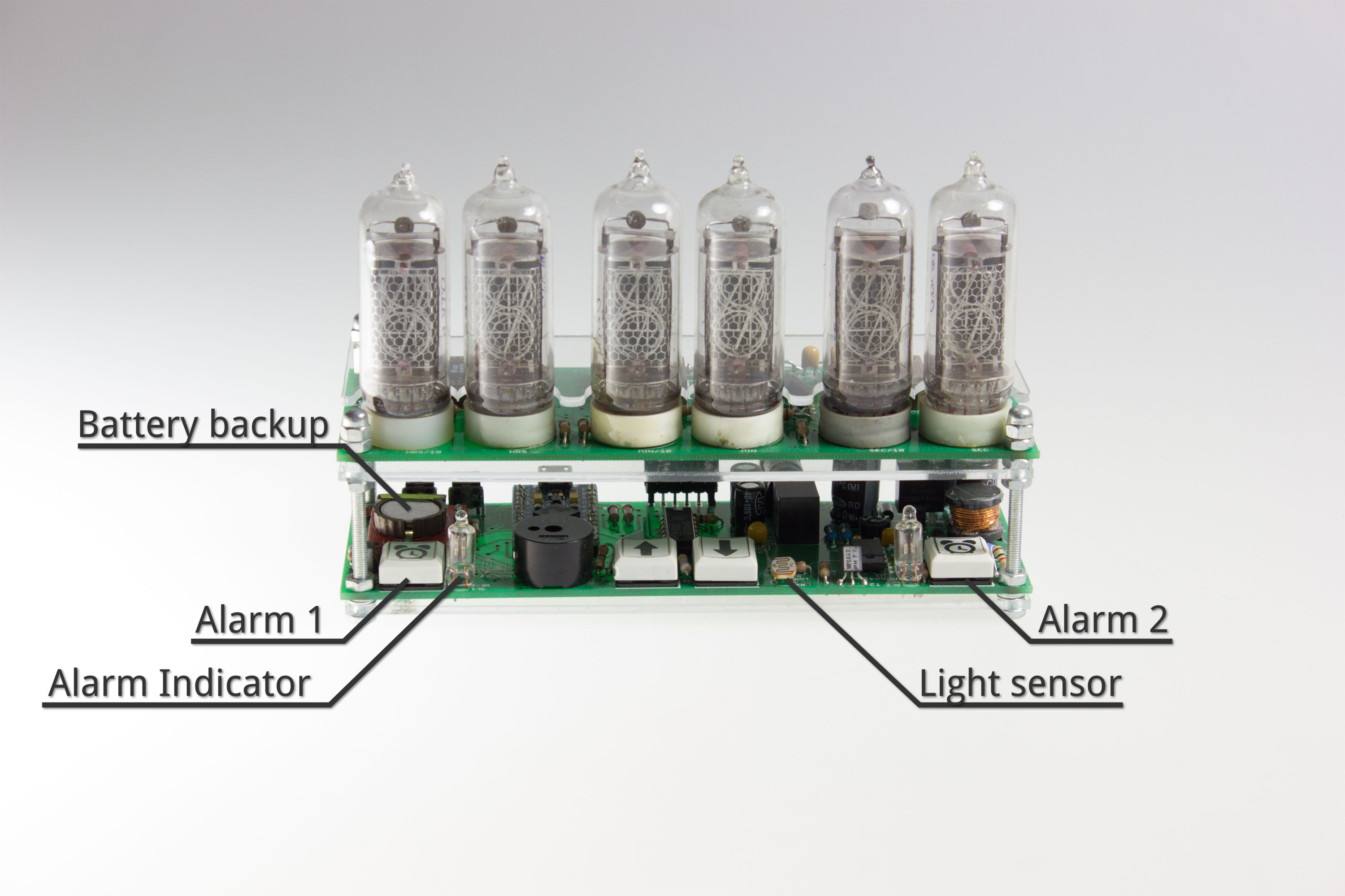
Rear view
The clock is fairly easy to operate since the nixie drivers only need 10 bits for each tube serially shifted in to control the cathodes. The RTC module is configured to output a 1 Hz pulse, which triggers an interrupt on the Arduino to read out the current time and feed this through to the display.
There are several features that I wanted to incorporate in the software. First of all, this will be my bedside clock and I don’t want to be blinded by it at night so the brightness should be adjustable. To achieve this I use the LDR to sense ambient brightness and control the nixie tube anodes using pulse width modulation (PWM) to dim their brightness accordingly.
Fading digits
Additionally, I wanted the digits to slowly fade from one time to the next. This is done by very quickly switching between the times that are displayed, and slowly adjusting the ratio between the previous and next time. Our eyes are very good integrators, so as long as the cycle time is short enough we perceive this as a smooth transition. This fading effect is actually something you wouldn’t see as it is quite difficult to implement using classic digital circuitry, yet it still adds a certain retro vibe to the display.
Next is a feature that is more or less required when you want a nixie display to look nice even after years of operation: cathode cleaning. When the same digit is displayed for a long time, this can “poison” cathodes around it by sputtering material onto them. When you try to power the other cathodes they might not glow evenly as a result. There is no ‘proven best’ method to prevent this, but my method is to cycle through all the digits randomly for a couple of seconds every 20 minutes. So far, after more than 5 years of operation, the tubes seem to glow exactly the same as when they started out. As an added bonus, I built an identical clock for a friend and he noted that his sense of time improved with the clock sitting on his desk as you can just can pick up the cycling digits out of the corner of your eye quite easily.
I implemented an alarm clock feature with two separately adjustable alarm times, using the aforementioned buzzer and two neon bulbs as indicators for which alarm is enabled. In practice I never use this in favour of the alarm on my phone as that one doesn’t sound like a fire alarm when going off, but it’s a nice feature to have on the clock nonetheless.
Finally, I implemented automatic daylight saving time adjustment so the clock practically only has to be adjusted for time drift.
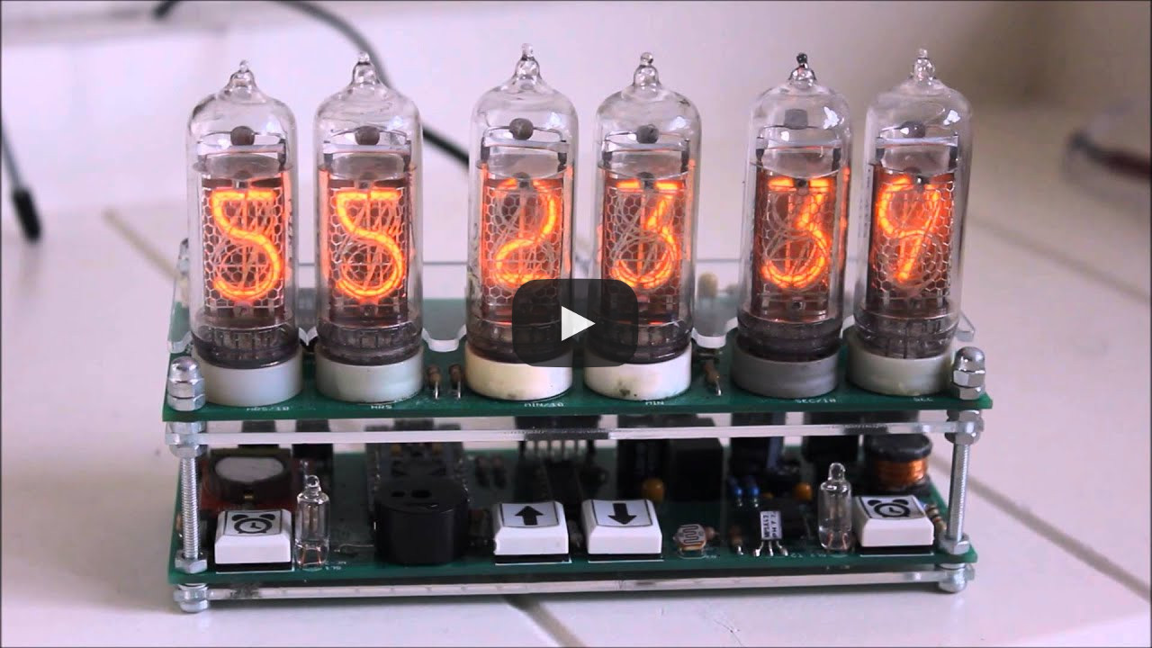
To wrap things up, a short video demonstration of the different features is shown below:
All design files and the Arduino code can be found on GitHub.
I have started work on a new version of the clock based around an ESP32 that should have a single PCB layout, lower BOM cost and a few other improvements. Don’t hold your breath though, it has reached the back of my project queue but I’ll write another post if that’s ever finished. In the mean time, check out my Dekatron spinner if you haven’t already.